- Set up Figure 3.3 of the Vector Voltmeter Manual, but omitting the 8491A pads. At 400 MHz and approximately 0.5 volts (on A), adjust the phase zero set for zero degree reading. Do not change the zero set after this. Interchange position of the two probes and record the two sets of readings for future reference. Check the amplitude and phase readings of the vector voltmeter over the 250-950 MHz range in steps of 50 MHz
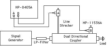
- Connect the circuit shown below.
- Repeat Part 2 for 600 and 900 MHz.
- With oscillator set at 300 MHz and a short-circuit termination (N-type) for a load, adjust the line stretcher for exactly 180 degrees phase, and find the N-type correction factor. Repeats parts 2 & 3 for the following assemblies of 50 W resistors, which are mounted on plates which use the same N-type connectors:
- 2- 100 W resistors
- 3- 150 W resistors
- 4- 200 W resistors (actually 2-180 and 2- 220 W resistors are used).
- Set the following circuit to use shorted shunt stub along with an adjustable length of line from stub to the load.
Obtain the impedance match at 600 MHz by adjusting stub length and the load length while checking for minimum value of the reflection coefficient (probe B). Compare these lengths to the computed lengths using the measured complex value of the load impedance.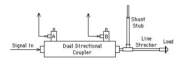
- Plot the normalized values of impedance on Smith charts.
- Discuss the Load Impedance variations as a function of frequency. Are these good 50 W loads at high freqeuncies?
With the oscillator set at 300 MHz, and a short circuit termination (GR type) for a load, adjust the line stretcher for exactly 180 degrees phase, and find the GR type correction factor g =Va/Vb. Replace the short circuit with a 47 W 1/2 watt resistor and measure the approximate reflection coefficient:

where Angle(q) = Angle(B) using Angle(A) as reference at 0o.
Find the exact reflection coefficient

c) Calculate the theoretical impedance of the resistor at this frequency, given the characteristic impedance of 50 W.