HP-8504A Vector Voltmeter
Front Panel Features
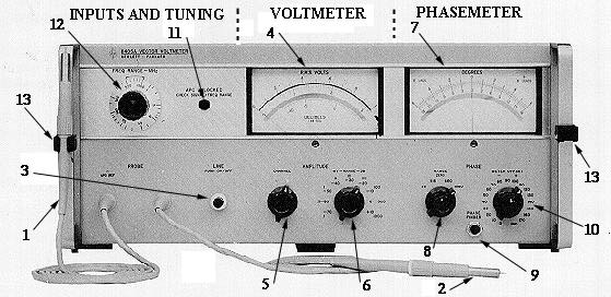
- Probe A. Input to channel A. The Voltmeter and Phase meter tune to probe A input frequency.
- Probe B. Input to channel B. A signal at probe A is required for phase measurement and for channel B amplitude measurement.
- LINE. Depress to turn on 8405A; lamp lights. Push button retainer unscrews for lamp replacement.
- AMPLITUDE Meter. Reads amplitude of fundamental component of signal applied to probe A or probe B.
- AMPLITUDE CHANNEL. Selects channel to be measured on voltmeter.
- AMPLITUDE RANGE. Sets AMPLITUDE meter scale.
- PHASE Meter. Reads phase angle between the fundamental components of signals applied to probes.
- PHASE RANGE. Set phase meter scale. Red ZERO control has at least ±10' range.
- PHASE FINDER. Overrides PHASE RANGE and PHASE METEROFFSET to select the ±180 phase range and zero offset. Used to find phase angle without changing settings of controls.
- PHASE METER OFFSET. Used to reduce input phase angle and allow use of expanded PHASE RANGE scales. Not usable unless a definite input angle exists.
- APC UNLOCKED. Lamp lights to indicate 8405A not tuned. Amplitude is too low and/or FREQ RANGE - MH Z selector is not set to the range which includes fundamental frequency of probe A input.
- FREQ RANGE - MHz. Coarse tuning control to put input signals within capture range of automatic fine tuning. Selected range must include fundamental frequency of signal applied to probe A.
- Probe Holder.
From: Page 3-0 of HP-8405A Manual
Back to
Experiment #1 or Home Page