Figure 3.3 of HP-8405 Manual
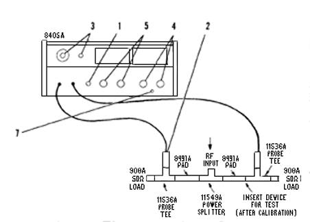
Figure 3-3. Transmission Line Measurements
CAUTION
Do NOT burn out probes. Maximum input: ±50 volts dc or 2 volts peak (4 volts pp). PotentiaI changes between test points should not exceed 50 volts dc to avoid transient pulses. Transient puIses greater than 50 V will burn out the probe. For this reason a blocking capacitor cannot be used in series with the probe to measure ac in a circuit with a dc potential of greater than 50 V.
- Connect equipment for calibration as shown above. Push LINE switch. Push button should glow.
- Apply signal to RF INPUT. Set AMPLITUDE CHANNEL to A.
- Set FREQ. RANGE-MHz to include measurement frequency. APC UNLOCKED light should go out showing that 8405A is tuned.
NOTE: Channel A input must be at least 1. 5 mV
(1-10 MHz); 300 mV (10-500 MHz); or 500 mV
(500-1000 MHz). (If input frequency is changed
within FREQ RANGE selected, APC UNLOCKED may flash every 1. 6 MHz. This is normal, 8405A is retuning.)
- Set PHASE RANGE to ±180, PHASE METER OFFSET to O, and adjust PHASE ZERO for zero phase meter reading. Switch RANGE to ±6 and re-zero as necessary.
- Set AMPLITUDE CHANNEL to B and AMPLITUDE RANGE to obtain on-scale voltmeter reading. Record reading.
- Insert device under test into circuit as shown above. Set AMPLITUDE RANGE to obtain on scale voltmeter reading. Residual attenuation or gain of device is difference between recorded reading of step 5 and voltmeter reading.
- Noting the PHASE Meter, push PHASE FINDER button. If meter needle goes to left (-) set METER OFFSET (red knob) to -; if to right (+) set METER OFFSET to +. Adjust METER OFFSET (black knob) for on-scale reading. To obtain phase reading, add meter reading and offset switch setting. For example, if offset setting is +50, meter reading is -4 and RANGE is ±6, then the actual angle is +46'.
From: Page 3-3 of HP-8405A Manual
Back to
Experiment #1 or Home Page