Calibration
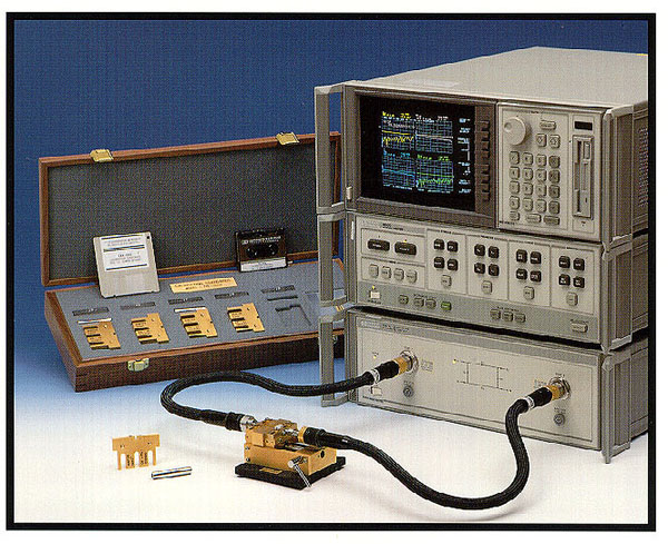
For the rest of the experiments that will be performed in this course, a sophisticated microprocessor controlled HP-8510 vector network analyzer with which precision microwave measurements can be made will be used. Please follow the instructions carefully. Every partner should repeat the calibration procedures.- Turn on the system in the following order: (Please refer to Network Analyzer Manual)
- Source (HP-8550B)
- Test set (HP-8515A)
- System peripherals (if used) plotter, printer, etc.
- Network analyzer (8510A)
- The network analyzer goes through out initiation and self-test. Once this is complete, press PRESET.
- Set Stimulus, Format and Response function blocks to your requirements. Familiarize yourself with these settings. Follow the sequences on the attached sheets.
- Calibrate the Network Analyzer for single port and then make the following measurements.
Experiments
- Load measurements.
Using the network analyzer, measure the loads that you have used in Experiments #1 at higher frequencies and observe the changes in load impedance values. - Cavity Q measurements.
- Measure the resonant frequencies and the Q of the cylindrical cavity up to 15.0 GHz.
- From the dimensions of the cavity (2a=18.0 mm and d=29.0 mm) find the theoretical modes that correspond to the experimentally measured resonant frequencies.
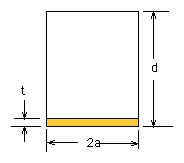
- Cavity perturbation.
Pick one of the lowest resonant modes of the cavity. Cut a very thin plastic sheet (thickness lot thinner than d) to a circular shape with a diameter equal to the diameter of the cylindrical cavity. Insert the plastic sheet into the cavity. Measure the shift in resonant frequency and change in Q of the cavity to observe the effects of the material perturbation of the cavity. This technique is used as a means to measure the dielectric constant and loss tangent of a dielectric material.
 Refer to Pozar, Section 6.8 (p.340) for the theory. Can you find the dielectric constant by following the theory given in the book? (extra credit)
Goto Homepage