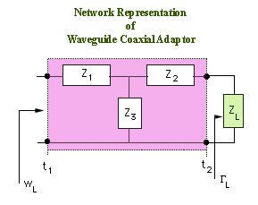
A waveguide-coaxial line adapter can be represented as a two port network. The two port network can be reprented by various parameters such as by Impedance elements, Admittance elements, S-paramters, and so on.
The figure above shows the Impedance representation of the adaptor. Here there are 3 complex elements (each elements has real and imaginary parts). If we assume the network to be lossless, then the elements are purely imaginary.
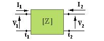
Rather than repesenting the impedances as arbitrary, they can be related to the total voltages at the terminal planes and the total currents entering these ports.The relation between the currents (taken as independent variables) and voltages (taken as dependent variables) can be written as a matrix equation
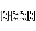
As a consequence of network being lossless, the network is also symmetric, i.e., Z12=Z21.
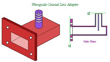
In a waveguide or coaxial transmission line, there are no means of measuring voltages and currents. We have to use parameters that we can measure with microwave instrumentation. The simplest is the measuremnt of reflected and transmitted signals. Once we measure these, we have to convert them to the necessary parameters that we are interested in (i.e., Impedance, Admittance, S-parameters, so on).
In order to introduce these concepts, we are going to use a simple waveguide-coaxial line transition adaptor as a means of introducing the idea of representation of this microwave component as a two port network.
