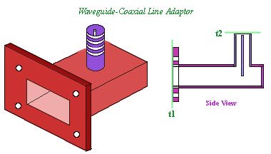
We are now going to characterize the Waveguide-Coaxial Adaptor by connecting various known impedances (a short-circuit, an open-circuit and a matched load) at one of the terminals and by making measurements through the second terminal. The known impedances connected at the first port are referred to as measurement standards.
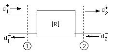
Figure shows the definition of the two port parameters for this Matrix. Here various d's represent the incident and reflected complex voltages at the corresponding ports. The now the ratios of these voltages can be mesured as corresoponding reflection coefficents at each port.
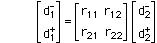
The corresponding [R] matrix can be written as:
If we connect a load ZL to Port 2, then the radio of (d2-/d2+) will be the load reflection coefficent GL.
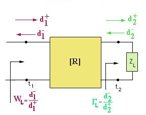 With the load connected at Port 2, the reflection coefficent at Port 1 will be WL=(d1-/d1+).
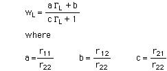
We can expand the [R] matrix equation given above and write it as a set of two equations. If we take the ratio of the resulting equations and simplify it, we can write it as
 .
.
If we now connect three loads with known reflection coefficients, we can measure the input reflection coefficients WL for each GL. This way we obtain three equations in the three unkowns (a,b and c). We can solve for the three unknowns (a,b and c). Finally, knowing these constants, we can calulate the [S] Matrix . Using the Matrix conversion equations we can determine the [Z] Matrix or [Y] Matrix , so on.
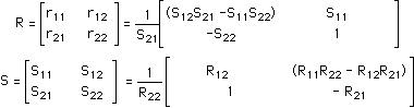
Finally the conversion equations between the [R] Matrix and [S] Matrix are given by: