University of Cincinnati
ECE&CS Department
EE-612
Microwave Communication Lab.
Prepared by: Prof.Altan M. Ferendeci
Experiment #2
Network Representation of a Coaxial-Waveguide Adapter
Purpose: Measure impedances using an VSWR meter. To characterize a coaxial-waveguide adapter as a two port network, to appreciate the calibration procedure in a network analyzer and to understand embedding networks .
Instrument to be used is a Standing wave ratio meter (VSWR).
Theory
A VSWR Meter can be used to measure impedances at microwave frequencies. By measuring the reflection coefficient at the input of an adapter and using known loads at the output terminal, one can determine the properties of the connector so that any load connected to the output terminal can be properly measured.
A coaxial line-wave guide adapter will be used for this purpose. Its impedance and scattering parameters will be calculated from the reflection coefficient measurements.
Experiment:
-
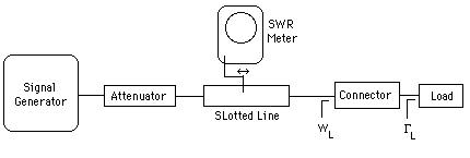
Part I. Connect a signal generator, an attenuator, a coaxial slotted-line, an extension cable and the load.
- At 3.0 and 4.0 GHz, measure the impedance of the loads that you have used in Experiment #1 using the (VSWR ) technique. Compare your measured data with the results of Experiments #1.
- For this, find the impedance of the load by first measuring the VSWR of the load and then by replacing the load by a short. From the shift in voltage minimum, find GL and calulate ZL.
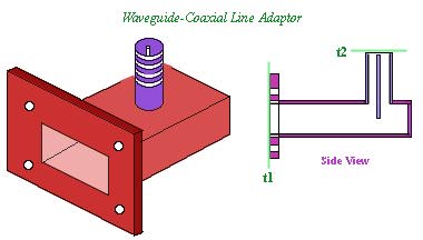
- Part II. Connect a signal generator, an attenuator, a waveguide slotted-line, an extension waveguide and a waveguide-coaxial line adapter as shown in the figure.
- Using a waveguide slotted line and a frequency of 10.0 and 11.0 GHz, measure the impedance of the 47 W load of Experiment #1 and compare with the low frequency measurements.
Part III: Calculate the [S] and [Z] parameters of the waveguide-coaxial line adapter using the modified wave amplitude matrix . This can be done by measuring the reflection coefficient wL of the connector plus various known loads (standards: Open, Short and Load).
- Measure first the reflection coefficient of the connector plus the standard and
then repeat the measurement by replacing the connector and standard by a short. From the shift in voltage minimum, calculate wL.
- For the load at the output of the connector, use a short, open and a matched load.
- Calculate a, b and c from these measurements
- Calculate the [S] and [Z] parameters of the adapters.
Reference: G.F. Engen and C.A.Hoer, "Thru-Reflect-Line" An Improved Technique for Calibrating the Dual Six-Port Automatic Network Analyzer", IEEE Trans. MTT.-27, 987-993(1979).
For determining the impedance from SWR measurements, refer to Pozar, Section 3.7, p-100,
Goto Homepage