University of Cincinnati
ECE&CS Department
EE-611
Microwave Communication
Prepared by: Prof.Altan M. Ferendeci
Voltage Standing Wave Ratio along a Transmission Line

The magnitude of the voltage wave along a transmission line can be written as (here z=-d )
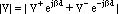
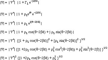
Factoring out |V+|
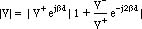
Substituting the load reflection coefficient
 for the ratio of (V+/V-), and manipulating the resultiing equation, we obtain
Maximum occurs when

here (n) is an integer, and

Minimum occurs when

here (n) is an integer, and

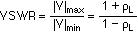
Voltage standing wave ratio (VSWR) is defined as
Notes:
- The length (d) given in Equations 1a and 2a are positive quantities. Therefore, the minus (-) signs in Eq.1a and 2a are to be excluded.
- If the integer n is set to zero (n=0 ) in Eq.1a, the distance from the load to the dmax is given by

- The distance between the two maxima is l/2. (half a wavelength) and between two minima is also l/2. The distance between a maximum and a minimum is equal to l/4 (quarter wavelength)
- If the load is purely real (resistive) and is less than the characteristic impedance Zc of the line, the voltage minimum occurs at this load location.
- If the load is purely real (resistive) and is greater than the characteristic impedance Zc of the line, the voltage maximum occurs at this load location.
As shown in the figure below and the accompanying Smith chart,
 To see an ANIMATION of this Figure click here
- The load is located at a distance from the first |V|max by the length
- As we move toward the generator on a constant rL radius (this also is the corresponding constant VSWR circle), the horizontal axis of the Smith chart is intersected. At this point the impedance is purely real and less than the characteristic impedance. Therefore this is the first location of the voltage minimum.
- As we move toward the generator along the constant rL radius, the real axis of the Smith chart is again intersected. But this time the impedance is again purely real but it is greater than the characteristic impedance of the line. Therefore, this corresponds to the first voltage maximum.
- The normalized impedance at the voltage maximum is also equal the VSWR on the line.
- As we move toward the generator, these mimima and maxima follow each other every quarter wavelength. As expected, the impedances repeat themselves every half a wavelength.
Measuremnt of Impedance Using VSWR Meter
- A short is used as a load and the locations of the voltage minima are recorded and
- The short is then replaced by an unknown load and the locations of the new voltage minima are recorded,
- From the shift in voltage minimum, the load reflection coeffient is calculated. Once this is known, the Impedance is calculated.
Copyright: A.M.Ferendeci, ECECS Dept.University of Cincinnati
Last Modified: Thu, Apr 9, 1998
Goto Experiment (1)
(2)
(3)
(4)
(5)
(6)
Goto AMF Homepage