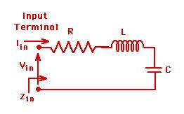
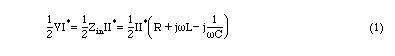
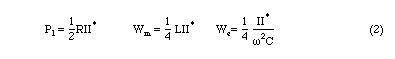
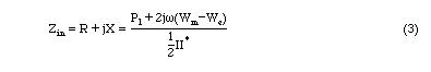
This has two terminals or a single port. It will be referred to as a one port network. Complex input power to this network is given by
Solving for Zin
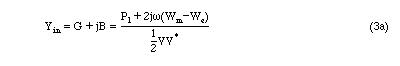
If we were to consider an equivalent parallel RLC network, the input admittance can be written (with a derivation similar to the series circuit) as
A one port microwave network can be visualized by
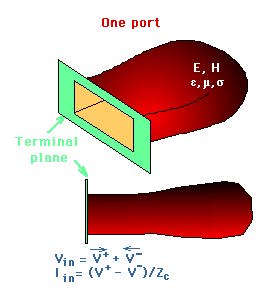
There is only one input where fields can enter into and leave out of the system. Since this has only a single input, it will be refrerred to as a one port microwave network.
A reference plane is chosen at a specfic input location. At this reference plane, power into and out of the network can be calculated in terms of the field quantities. Within the network, there will be power dissipated due to the finite conductivity of the walls as well as the presence of lossy dielectric or magnetic materials. The electric and magnetic energies associated with the fields can also be computed. Therefore at the input port of a microwave network an equivalent one port input impedance can be defined similar to the RLC series (or parallel) network. The equivalent input impedance can be written similar to Eq. 3.
Note that associated with the Electric Field, we were able to write an equivalent travelling voltage wave for a transmission line. Also, associated with the magnetic field,an equivalent travelling current wave was written before. At the chosen terminal plane of the one-port network, these will have specific complex values. These are repesented in the figure above as
Vin=(V++V-) and Iin=(I+-I-)=(V+-V-)/Zc.
For the charateristic impedance:
- charateristic impedance of a transmission line for TEM waves
- ZTE impedance of the TE modes and
- ZTM impedance of the TM modes
are used.
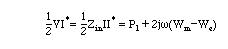
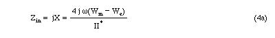
Many microwave networks can be assumed to be lossless (small losses can be neglected), i.e., Pl=0. In this case, for a one port network, Eq.3 reduces to
And for the parallel network

Input reactance (or susceptance) can be zero if Wm=We. This is the resonance condition. It implies that either
The above concepts can be generalized to N-port networks.