University of Cincinnati--ECE&CS Department
Impedance Concepts in Microwave Frequencies
N-Port networks
Prepared by: Prof.Altan M. Ferendeci
N-Port Networks
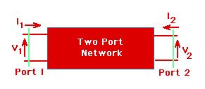
A typical Two-Port network is shown in the figure below.
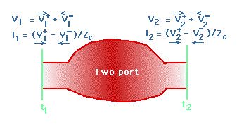
Again two reference planes are chosen; one for the input and one for the output. The E and H fields entering and leaving the ports are replaced by the incident and reflected voltage and current amplitudes.
As a convention, the current directions are taken as entering into the network.
The following figure shows an N-port microwave network
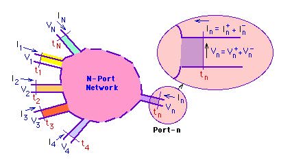
If each mechanical port supports a single mode of propagating field, it can be represented as an electrical port. If in a given mechanical port, more than one mode of propagating fields are supported, than that mechanical port will be represented by that many electrical ports. In many practical cases, only one mode propagates through a given port. Therefore, the above complication is removed.
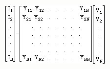
The dependent variables ( total voltages) at each port can be related to the independent variables ( total currents) at each port through the [Z] matrix defined by
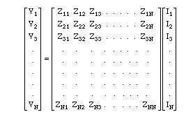
in short hand notation
[V]=[Z][I]
The elements Zij are can be found by
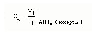
i.e.,
- by open-circuiting all the other ports, except i'th port,
- by applying a voltage source at port j,
- by measuring current at j'th port (Ij), the total current at port j, and Vi, the voltage at port i.
- The ratio of Vi/Ij gives Zij.
Similarly, an admittance matrix is defined by relating Currents to Voltages through
in short
[I]=[Y][V]
The elements Yij are found by
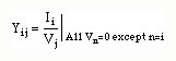
i.e.,
- by short circuiting all the other ports, except i'th port,
- by applying a voltage source Vj at port j, and
- by measuring Ii, the total current at port i.
The ratio of Ii/Vj gives Yij.
Properties of lossless Networks.
- The rate of change of reactance (or susceptance) as a function of w is positive. This is Foster's Reactance Theorem. The result implies that the poles and zeros of a reactance (or susceptance) function alternate in position along the w axis.
- Even and odd properties of Zin =R(w) + JX(w) for a single port microwave network
R (-w) = R(w) (even function) and X(-w) = -X(w) (odd function)
- For networks with linear e and m, the impedance (admittance) matrix is symmetric. i.e.,
Zij =Zji or Yij =Yji
- Impedance and admittance matrices are reciprocal of each other. i.e.,

- For a lossless network, Re (Znm) =0. i.e., the network elements are purely imaginary.
Examples of Two port networks
.
- Coax-Waveguide adapter.
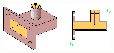
- Coax-Microstrip fixture.

- Waveguide transition
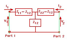
Typical representation of the two port network will be
And as a T-network
Copyright; Altan M. Ferendeci, University of Cincinnati