The importance of b will be explained shortly. The total current density at any position x can be written as the sum of the particle current density and the displacement current density.
Solving this for E(x), we obtain
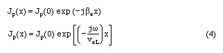
The spatial dependence of the a.c. particle current density can be written as
Here be is the electron phase constant defined by w/vsL. If both sides of Eq.3 are multiplied by dx and integrated form 0 to L, the left side becomes equal to the applied potential. Integrating the right side, and using Eq.4, we obtain
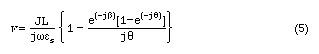
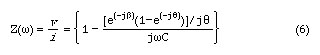
Here q is the transit angle and is equal to (wL/vsL). Multiplying and dividing the right side of Eq.5 by the cross sectional area A of the bar and defining the capacitance of the bar as C = (esA/ L), the a.c. impedance of the bar can be written as
Taking the real and imaginary parts of Z(w) , we obtain
and
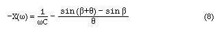
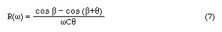
Due to the causality, the injected electron phase has to be equal to or greater than zero, i.e., b >=0. For b = 0 , what ever the value of q is, R>0. On the other hand, for 0 < b < p/2, R will admit negative values. Maximum value of cosb - cos (b + q) = -1 will occur if b = p /2 and q = 3 p /2 . Due to presence of q in the denominator in Eq.7, the actual maximum negative resistance is achieved for somewhat lower values of q, but the optimum value still occurs for b=p/2. The angle q, that maximizes Eq.7. b is found from the direct solution of the transdental equation tanq=q which gives for q = 257.5 degrees.

The phase of the injected current is given by

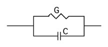
To get b=p/2 implies that wC>>G. However this means that the magnitude of the particle current is only a fraction of the total current. This will lead to a very small negative resistance. For this diode, the most favorable condition may be obtained for wC=G.
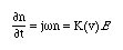
which shows that the phase difference between the n and E will be exactly equal to 90o. We can, therefore, conclude that the avalanche breakdown should be a very effective injection mechanism.
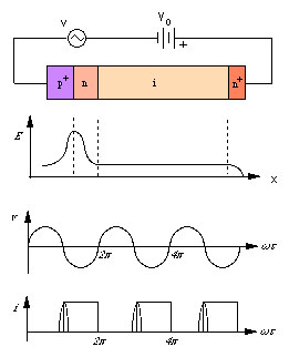
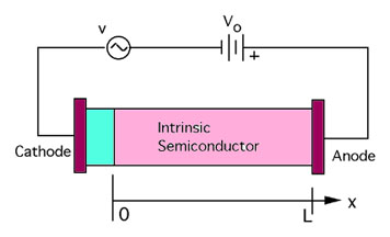
Due to the very high field across the p+-n junction, electron-hole pairs are generated. The holes quickly enter the p+ region. The generated electrons are injected into the drift space where they drift toward the n+ ohmic contact with a constant vsL.
As the a.c. electric field E, which is directly proportional to the applied a.c. signal voltage v, varies around an average value, the impact ionization rate per carrier follows field changes nearly instantaneously. However, the carrier density does not follow the field change in unison, because the carrier generation also depends on the number of electrons already present at that instant. Even after the field has passed its maximum value, the carrier density keeps increasing because the carrier density is still above average value. The maximum charge carrier density is reached approximately when the field decreases from the peak value. Although the ionization rate is in phase with the field, the a.c. variation of the carrier density thus lags ionization by about 90o.
The above situation is illustrated as the injected current in Fig.3d. The peak value of a.c. field occurs at q=p/2, but the peak of the injected current occurs at q=p. The injected electrons then enter the drift region where they move with constant vsL . Comparing the a.c. field with the external current, it is clear that the diode exhibits negative resistance at its terminals since the particle motion through the intrinsic region occurs under the influence of the D.C. bias during the negative cycle of the a.c. signal. That is, the phase difference between the voltage and current becomes 180o.