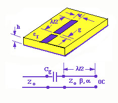
The length of the isolated resonator is l/2. The resonator is excited by a gap coupled microstrip line of characteristic impedance Zo as shown in the figure below. The gap can be considered as a capacitor and the equivalent circuit of the resonant circuit is also shown in the figure.
The normalized input impedance can be written as
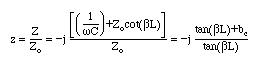
Resonance condition is obtained when the imaginary part of Zin=0. This leads to

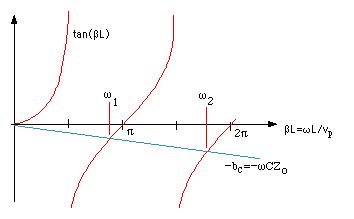
This can be solved analytically to find the resonance frequencies of the system. A graphical solution is also possible as shown in the figure below. Instead of the resonance occurring at wo for the isolated line, the resonance is shifted to a lower frequency w1 as shown in the figure below.
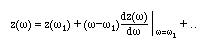
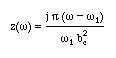
The normalized impedance in the vicinity of w1 can be found from
Using the given z(w)
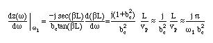
This is similar to the series resonant circuit. Even though the isolated l/2 open circuited line is equivalent to a parallel resonant circuit, the effect of the coupling capacitor has modified the resonance properties of the line.
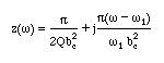
Losses can simply be included by the simple transformation and gives
Coupling coefficient is defined for this circuit as

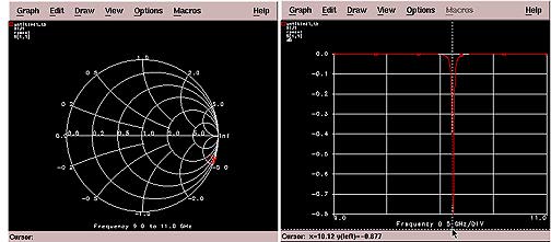
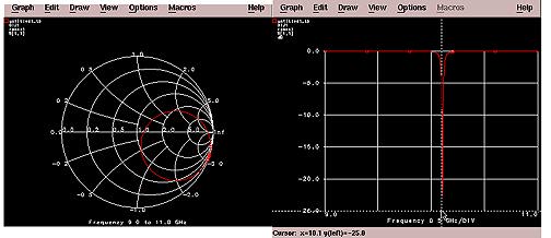
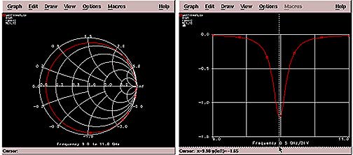
Depending on the magnitude of g, the circuit is said to be
Microstrip line
Gaps=1.0 mm, 0.5 mm, 0.01 mm