 (1)
(1)Supplementary Notes
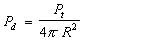
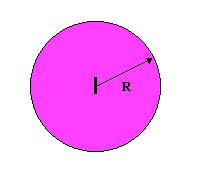
Note that if we divide the total power radiated (Pt) by the area over which it is distributed, we obtain the relationship
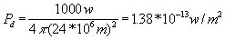
(1)where Pd is called the power density; Pt is in watts; and the denominator is given in units of area. For example, if the total radiated power (Pt) is 1000 watts and the distance from the source (R) is 24,000 km, then the power density (Pd) at any point on the chosen sphere is
Notes:
A certain moon-to-earth relay satellite has a receiving antenna whose effective area is 5.3 m2 . The satellite is located 36,000 km above the earth's surface, and receives a power of 5 x 10-14 watts from a lunar transmitter when the two bodies are closest. Assuming the moon-based transmitter is an isotropic source, what power must it radiate?
(Note: Free-space conditions are approximated in satellite communication systems.)
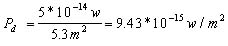
The distance R between the satellite and the moon may be calculated as follows:
average earth-to-moon distance' = 384,000 km
earth-to-satellite distance = 36,000 km
closest satellite-to-moon distance is 384,000 - 36,000 = R = 348,000 km
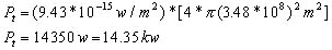
While the isotropic source is useful in conveying the conceptual idea of power density, any such practical radiator is not usually useful. For example, consider the situation of the satellite communication network- mentioned in Example 1. Here, it was seen that 14350 W had to be distributed in every possible direction in order to achieve the desired power reception at only one particular point. Such an inefficient system represents a monumental waste of energy. Indeed, if the transmitted power could have been concentrated somehow, much less transmitted power will be needed to obtain the same required receiver power.
Most practical antennas are not isotropic, but rather radiate better in one particular direction than any other. These antennas are said to have directivity or directive gain compared to an isotropic source.
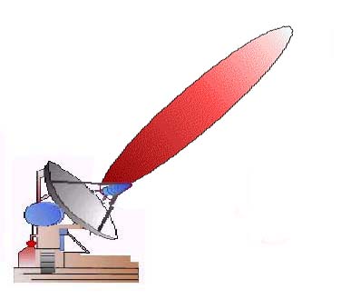
For example, the power density of a test antenna Pd(test) as measured along the axis of maximum radiation will be greater than that of an isotropic antenna Pd(isot) when both are fed the same input power and measured at the same distance. We then define the directive gain (Gd) of the test antenna as
 (2)
(2)The ratio expressing the antenna gain is more often given in decibels as:
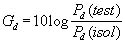 (3)
(3)
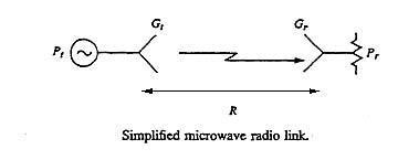
If the transmitting antenna has a directive gain ratio Gt, then the power density along the axis of maximum radiation will be
 (4)
(4)The power received (Pr) by an antenna oriented for maximum reception depends upon its aperture (i.e., effective area, Ar, and is given by
 (5)
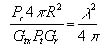
(5)Since it may be shown that the ratio of aperture to directive gain (A / G) is the same as the ratio (l2/4p) , we may relate equations (1) and (5) to obtain a useful expression for signal attenuation in free-space transmission. From equation 5,
 (6)
(6)Using equations (1),
 (7)
(7)Using equation (5)
 (8)
(8)Rearranging terms and using l=c/f,
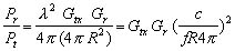 (9)
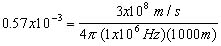
(9)Equation(9) is known as Friss Power Transmission Formula. If f is given in MHz and the distance is given in kilometers, this equation can be written as
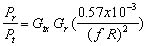 (10)
(10) where
Upon expressing the power ratios in decibel, we obtain
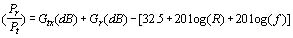
As can be seen from this equation, most of the signal loss is in free space.
)
)