A transmission line having a length of lg/4 at the design frequency can be used to transform a real impedance to a diferent real impedance value.
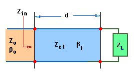
Consider a load ZL is connected to a short transmission line of length d, characteristic impedance of Zc1 and propagation constant of b1. This line is then connected to second transmission line having a characteristic impedance of Zo as shown below.
The input impedance at the output of the line of length d is given by
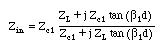
If the line length d is a quarter wavelength long, then
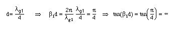
This means that
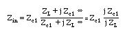
or finally

A transmission line having a length equal to a quarter-wavelength is said to invert a given load.
This inversion property of the quarter-wavelength lines can be used to transform impedances and are known as quarter-wave transformers
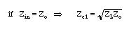
Consider now the second line having the characteristic impedance of Zo. This line sees the input impedance Zin calculated above as an equivalent load connected to its terminals. If we require this line not to have any reflections at this juntion, then the input impedance should be equal to the characteristic impedance Zo of this second line. Equating Zin to Zo and solving for Zc1, we find that
Since the impedances Zo and Zc1 are real for practical transmission lines, the equation can hold true if the load ZL is also real.
Thus a line having a quarter-wavelength long can be used to transform real impedances. This type of applications can be easily implemented using planar transmission lines such as microstrip, stripline, and so on.
Solution