As an example, a transmitting antenna can be given. Here the antenna terminals may present a complex impedance. The antenna is supplied by a source which has a real source impedance or a transmission line which has a real characteristic impedance.

The aim is to use a matching network so at the input terminals
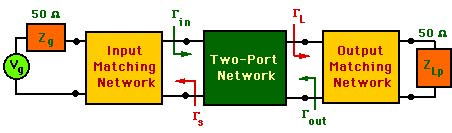
As an example for this a transistor amplifier can be used. The block diagram of a microwave amlifiere is shown in the figure below.
The aim is to design the input and output circuits so that maximum power is transferred from the source to the load. In order to achieve this, the following conditions should be satisfied (these may not be possible for all amplifer circuits)
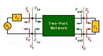
In an actual circuit, the source and load may be connected to generators and transmission lines which have real characteristic impedances. The actual circuit may look like the following:
Therefore, the aim is to transform the load and the generator impedances to complex impedances (or admittances) (or omplex reflection coefficents)