Lumped lossless elements such as inductors and capacitors.can be used for matching purposes. The inductors and Capacitors are assumed to be ideal. Low loss inductors and capacitors can easily be implemented using integrated circuit processing techniques.
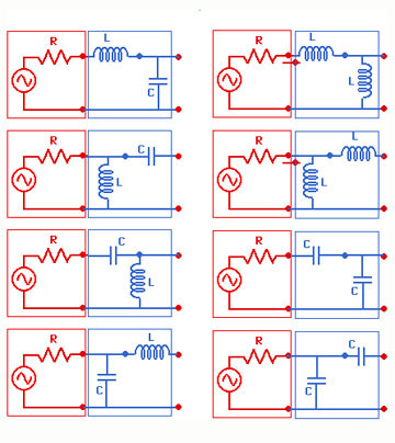
The following figure shows some possible combinations of using inductors and capacitors for matching puropses. In these circuits, usually 50 W source impednace is transformed into a complex impedance. The sourse can also be replaced by a load without any generator. This is usually a ciruit used at the output matching of the transistor amplifiers.
Note that capacitors and inductors can be used in series and in parallel with the other elements. Thus during the design, one has to move back and forth between the the impedance and admittance charts.
It is therefore advisable to use Combined Impedance-Admittance Chart instead of using a single Smith chart.
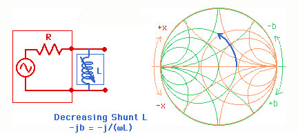
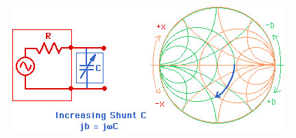
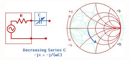
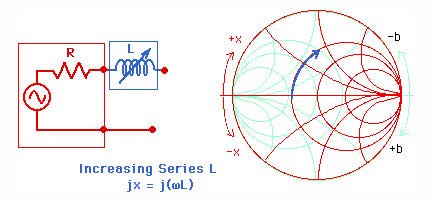
The following figures show the way the changes in inductor and capacitor values are reflected on the Smith chart. Note that we have to use the admittance chart for shunt elements and impedance chart for the series elements.
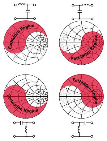
It is not possible to match impedances with all the above possible combinations of L's and C's. There are forbidden regions. Figure below shows the forbidden regions for four combinations of matching networks. These are for transforming 50 W into a complex impedance.