University of Cincinnati-
ECE&CS Department
Microwave Communications
Prepared by: Prof.Altan M. Ferendeci
Matching Networks: Distributed Elements
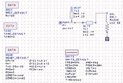
This example shows the results of calculations and simulations of a matching network using distributed elements.
The aim is to match a complex load ZL=200+j160 W to a 100 W line
. Frequency 10 GHz.
- First calculate the value of the inductance L from XL=160=(2p1010)L. L=2.55x10⁻⁹ H
- Either calculate or use the Smith Chart to find the necessery lengths of the transmission lines. Note: there are two solutions. Refer to Matching a Complex Load to a Real Impedance for the procedure and identification of the symbols.
- lengths of the transmission lines: d1=0.213l, (second solution d1=0.370l)
- lengths of shunt stubs: d2=0.352l, (Second solution d2,0.148l)
- Use the Line_Calc to find the physical widths and lengths of the transmission lines (Zc=100W). For only the first choice:
- w=0.136 mm
- d1=2.540 mm
- d2=4.202 mm
- Use HP_Libra to simulate the circuit.
Things to be careful in the simulations:
- Be sure that you have the default data items changed in the default directory. Just including them without the extension _DEFAULT does not provide the necessary changes.
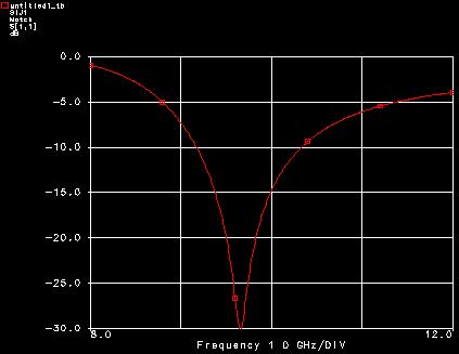
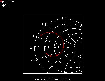
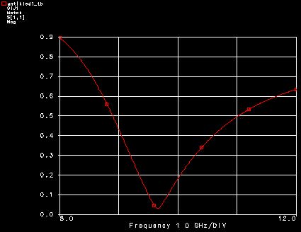
- You can plot the results on a linear or log scale or on a Smith Chart.
- Even though match was made at 10 GHz, the simulations show a match at a slightly lower frequency. This is due to slight errors in the values that were entered into the simulations. By an optimication process, the match can be moved to 10 GHz.
The following figures display the results of the simulations:

Back to Microwave Communications
Copyright; Altan M. Ferendeci, University of Cincinnati