University of Cincinnati-
ECE&CS Department
Microwave Communications
Prepared by: Prof.Altan M. Ferendeci
Matching Networks: Example
This example shows the results of using a quarter wave transformer.
The quarter wave transformer transforms the 50 W into a real impedance (less than or greater than 50 W) which is followed by a short length of a transmission line which brings the impedance to the required impedance level (or admittance or reflection coefficent value).
- Draw a circle with the radius equal to the required reflection coefficient magnitude (green arc).
- Transform 50 W to a higher (or lower) impedance. This impedance is obtained from the intersection of the refkction coefficent circle and the real axis (red line)
- Read the impedance from the Smith Chart
- Find the necessary charateristic impedance of the quarter wave transformer
- Read the lenght of the 50 W transmission line which will transform this impedance into the required input impedance.
- You can then find the necessary physical lengths of the matching networks.
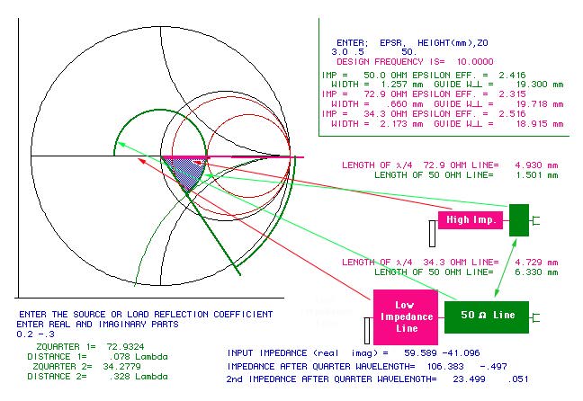
Note: There are two solutions to this matching network.
Back to Microwave Communications
Copyright; Altan M. Ferendeci, University of Cincinnati