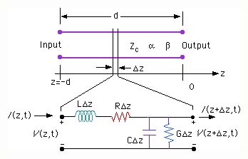
Next we consider an incremental length Dz of the transmissions line as shown in the figure above. For this incremental length, let the respective input voltage and current be V(z,t) and I(z,t) and the output voltage and current be V(z+Dz,t) and I(z+Dz,t).
There are four circuit parameters that we have to consider:
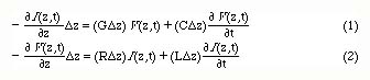
The voltage drop between the input and output can be written as
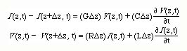
Here RDz is the series resistance and LDz is the series inductance of the incremental line of length Dz. CDz is the shunt capacitance and GDz is the shunt conductance of the incremental line of length Dz.
Expanding the current and voltage in the vicinity of z, The above equations can be written in the form
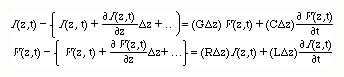
Simplifying the equations, we obtain
Taking the time derivative of the first equation and the space derivative of the second equation
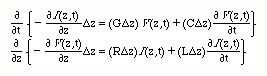
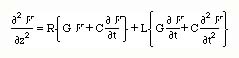
and eliminating  between the two equations, one can write
We now assume a sinusoidal signal of frequency of w propagating along the line. Using the phasor notation for the voltage Vejwt, the above equation simplifies to,
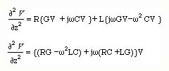
We can write this equation as

The solution of this equation is simply,
If this equation is multiplied by ejwt, it can be seen that the first term is a positively traveling voltage wave and the second term is a negatively traveling voltage wave.
If we have taken the space derivative of Eq.1 and time derivative of Eq.2, manipulated the resuting equations, we would have obtained exactly the same equation for the current as for the voltage. Solution of this equation will give
Again we obtain a positively and negatively traveling current waves along the transmission line at any point z.
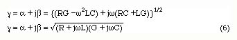
The quantity g is the complex propagation constant and is given by
In order to find a relation between the positively traveling voltage and current waves, we write Equations 1 & 2 in phasor notation as
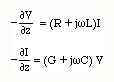
Substituting the positively traveling voltage and current waves into the first equation above, we obtain
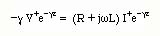
We now define an impedance Zc as the ratio of V+/I+
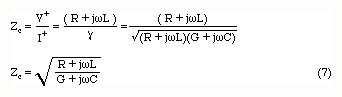
This is called the characteristic impedance of the line.
Using the negatively traveling voltage and current waves, we find a similar expression but with the ratio V-/I- having
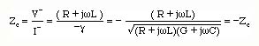
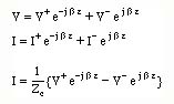
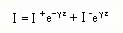
Thus the total current wave along the transmission line can also be written in terms of the voltages.
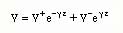
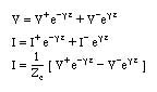
In summary, the total voltage and current on a transmission line at a point z along the line can be written as
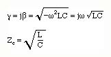
For a lossless line, R=0 and G=0. The propagation constant and the characteristic impedance becomes
For short lines with small losses, the losses can be neglected and the voltage and current waves become