ECES 349
MEASUREMENTS
LAB
Experiment #7
Curve Tracer
1. Design a simple curve tracer and use it with the scope X-Y to trace typical I-V curves for electronic parts.
A simple two terminal curve tracer can be implemented using the following simple circuit.
http://www.techlib.com/electronics/curvetrace.html

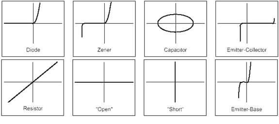
Display the I-V characteristics of some of the following devices.
2. You can also use the 555 timer to implement a curve tracer. It will be left to you to find a 555 circuit that will generate a sinusoidal or saw tooth voltage. Be careful how you apply the ground terminal. Use this circuit as a source to sweep the voltages and reading currents on the oscilloscope.
A typical circuit is shown below
Experiment_7
Use the sawtooth generator that you have assembled and test the I-V charateristic of the diode that you have measured in part 1. Compare the two measruments
Circuit diagram: http://www.electronic-circuits-diagrams.com/oscillatorsimages/2.gif
1- Obtain scope screen copies showing all characteristic curves of typical devices.
2- Is there a difference in the slopes of the
curves in the positive and negative voltage ranges for the diodes?
3- Explain whether you obtained the actual
currents flowing through the diodes?